
How Do You Install and Wire a Cam Operated Rotary Switch Correctly
2026-03-09
Proper installation of a Cam Operated Rotary Switch ensures operational safety and equipment longevity. Lixin provides high-quality switching solutions designed for industrial control panels, motor controls, and changeover applications. This guide explains the correct procedures for mounting and wiring these versatile devices.
Understanding Cam Operated Rotary Switch Terminals
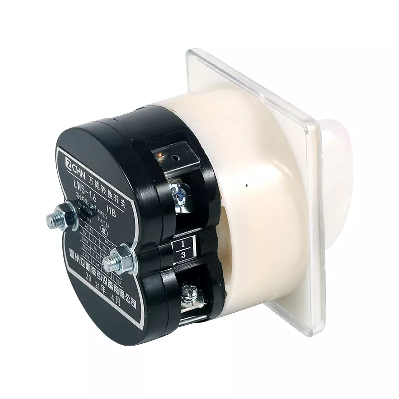
Before beginning installation, identify the terminal configurations. A typical Cam Operated Rotary Switch from Lixin features clearly marked terminals and a position indicator.
| Switch Type | Typical Poles | Common Applications |
|---|---|---|
| Cam Switch | 2-12 poles | Motor control, changeover |
| Selector Switch | 2-4 positions | Mode selection, isolation |
| Multimeter Switch | Multiple decks | Measuring instrument selection |
Tools Required for Installation
-
Voltage tester
-
Screwdriver set (Phillips and flathead)
-
Wire strippers
-
Multimeter for continuity testing
-
Panel mounting hardware
Step-by-Step Wiring Procedure
1. Safety Preparation
Disconnect main power supply completely. Verify absence of voltage using a calibrated tester. The Cam Operated Rotary Switch must be in OFF position before starting.
2. Panel Mounting
Insert the switch into the panel cutout. Secure using the provided mounting nut. Lixin switches include anti-rotation washers to prevent movement during operation.
3. Terminal Identification
Refer to the wiring diagram provided with your Cam Operated Rotary Switch. Terminal numbers correspond to specific contact sequences.
4. Wire Connection
Strip wires to appropriate length. Insert into terminal clamps and tighten securely. Pull test each connection to verify proper grip.
5. Contact Sequence Verification
Use a multimeter to check continuity across contacts in each switch position. This confirms correct wiring before power application.
Wiring Diagram Example
For a typical 3-position Cam Operated Rotary Switch:
| Position | Terminals Connected | Function |
|---|---|---|
| OFF | None connected | Isolated |
| Position 1 | 1-2, 3-4 | Circuit A active |
| Position 2 | 1-3, 2-4 | Circuit B active |
Cam Operated Rotary Switch FAQ
Question: What is the difference between maintaining and momentary contact types in a Cam Operated Rotary Switch?
Answer: Maintaining contact switches remain in the selected position until manually changed. These are common for mode selection. Momentary contact switches return to a default position when released, typically used for jogging or testing functions. Lixin manufactures both types with silver-alloy contacts for reliable performance.
Question: How do I determine the correct current rating for my Cam Operated Rotary Switch application?
Answer: Calculate the full load current of your connected equipment. Select a switch rated for at least 125% of this value for inductive loads like motors, or 110% for resistive loads. Cam Operated Rotary Switch ratings indicate thermal current (Ith) and operational power. Lixin switches include clear rating labels for easy identification.
Question: Can a Cam Operated Rotary Switch be used for both single-phase and three-phase applications?
Answer: Yes, depending on the pole configuration. Single-phase applications typically use 2-pole or 4-pole switches. Three-phase applications require 3-pole, 4-pole, or 6-pole switches depending on whether neutral switching is needed. Always verify the contact configuration matches your circuit requirements before installation.
Common Wiring Mistakes to Avoid
-
Overtightening terminals which damages contacts
-
Using incorrect wire gauge for current rating
-
Ignoring minimum clearance requirements around the switch
-
Failing to secure cables against vibration
Testing After Installation
-
Rotate through all positions without power
-
Verify smooth operation and definite detent feel
-
Apply power and test voltage at output terminals
-
Check for proper sequence in all positions
Contact Us
For technical specifications or assistance selecting the right Cam Operated Rotary Switch for your application, contact Lixin today. Our engineering team provides wiring diagrams and installation support for all industrial switching requirements. Reach out for a quote or customized switch configurations.